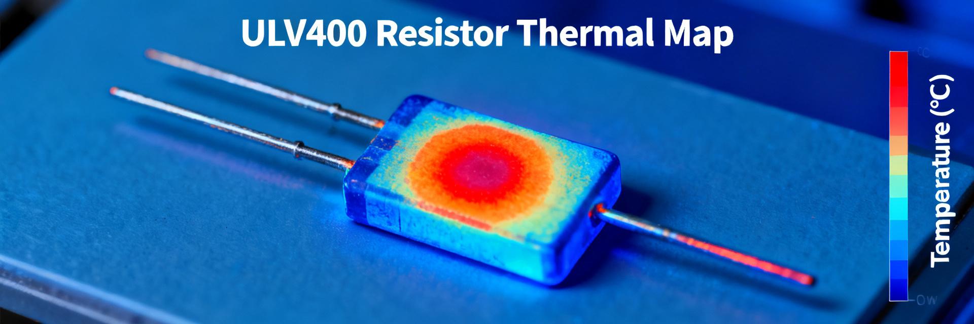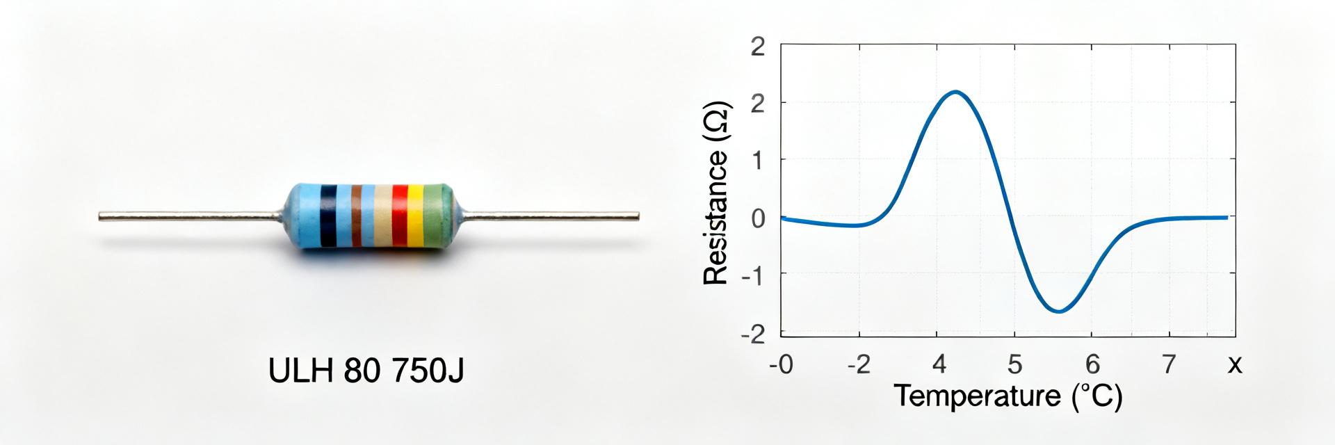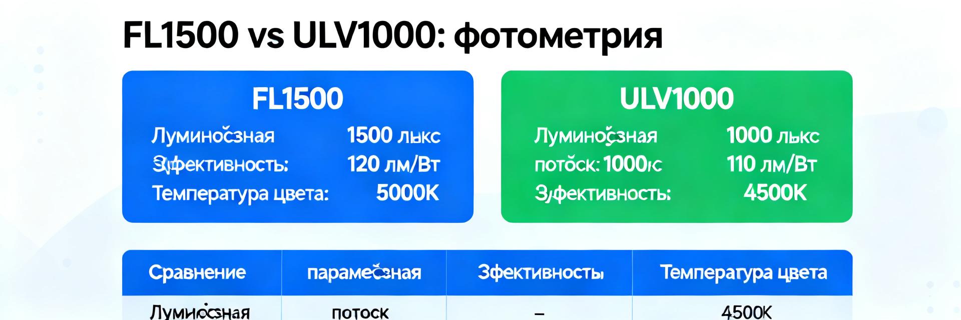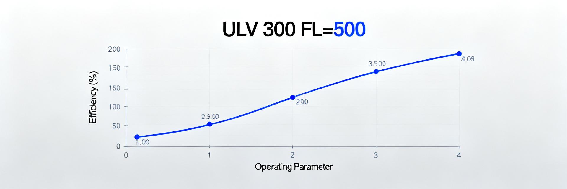
Introduction: Analysis of the datasheet shows that correct selection and application of ULV 500 type resistors critically depend on considering electrical and thermal parameters under the condition FL=500. ULV 500 75 J FL=500 is used in high-power nodes and heavily loaded test benches where nominal power, pulse withstand capability, and temperature stability are essential.
Briefly: This article relies on systematic datasheet reading and typical test protocols, providing data selection methods, measurement metrics, and a checklist for selection/calculation. The goal is to give engineers a compact but comprehensive set of rules for resistance selection and derating assessment under real operating conditions.
1. Background: What is the ULV 500 Resistor and How to Read the Datasheet

The first step in reading the datasheet is identifying the construction, package type, and element materials. For the ULV 500 series, not only the nominal value and tolerance are important, but also structural parameters: package type, deposition technology, nominal power at FL=500, and EMI/moisture protection parameters. Based on this, suitability for a specific application is assessed.
| Parameter | Condition / Specification | ULV 500 Value | Unit |
|---|---|---|---|
| Nominal Power ($P_{nom}$) | Heatsink mount, FL=500 | 500 | W |
| Thermal Resistance ($R_{th}$) | Case-to-heatsink (with TIM paste) | ≤ 0.28 | °C/W |
| Max Operating Temperature ($T_{max}$) | Active layer temperature | +175 | °C |
| Isolation Voltage ($V_{iso}$) | 50 Hz, 1 min, leads-case | 2500 | V |
1.1 Construction, Purpose, and Typical Application Areas
Point: Construction determines thermal capacity and pulse withstand capability. Evidence: The datasheet specifies package type, resistive layer material, and mounting method. Explanation: The package and deposition technology (cermet, wirewound, metal foil) determine pulse capability, Tmax, and mechanical reliability, which are critical for power and heavily loaded installations.
1.2 Decoding FL=500 — How and Where to Find the Exact Value in the Datasheet
Point: FL=500 in the datasheet denotes test conditions or a correction factor for thermal assessment. Evidence: Manufacturers and manuals indicate FL as a factor affecting nominal power under a fixed mounting configuration. Explanation: When reading, look for notes on power tables and power vs. temperature curves to verify FL=500 and measurement conditions.
2. Key Electrical Parameters at FL=500
2.1 Resistance, Tolerance, Nominal Current, Maximum Allowable Voltage
Point: Basic electrical parameters are nominal R, tolerance, and maximum operating current. Evidence: The datasheet contains tables of nominal values and limit currents for different resistances at FL=500. Explanation: During selection, required current and voltage must be cross-checked against table values, considering cold start possibilities and pulse overloads; in case of discrepancies, choose a higher class or use parallel/series connections.
2.2 Temperature Coefficient (TCR), Noise, Pulse Withstand Capability, and Overload Modes
Point: TCR and noise affect accuracy in sensitive circuits; pulse withstand capability affects survival during short-term overloads. Evidence: Datasheets typically provide TCR in ppm/°C, pulse power graphs, and recommended pulse shapes. Explanation: At FL=500, select a resistor with low TCR for stable sensitive applications and verify characteristics based on pulse energy at the specified pulse duration.
3. Thermal Parameters and Derating for ULV 500 at FL=500
3.1 Thermal Resistance (Rth), Maximum Operating Temperature, and Thermal Capacity
Point: Rth determines how effectively the element dissipates heat to the environment or heatsink. Evidence: The datasheet provides Rth for various mounting methods — on PCB, on heatsink, in enclosure. Explanation: Calculation ΔT = P × Rth gives the expected temperature rise; during design, consider Tmax limits and choose mounting/heat dissipation to keep operating temperature within safe ranges.
3.2 Derating Curve and Calculation of Allowable Power at Different Tamb and FL=500
Point: Derating shows the reduction in allowable power as ambient temperature increases. Evidence: Technical descriptions usually include derating graphs from +25°C to +125°C. Explanation: Engineers need to translate nominal power to mounting conditions by applying graphs and correction factors, and provide a safety margin for mounting and heat dissipation if necessary.
4. Testing Methods and Practical Parameter Measurements
4.1 Laboratory Methodology: Equipment, Test Bench, and Test Sequence
Point: Reproducibility of results depends on the test bench and measurement sequence. Evidence: Testing standards describe sample preparation, heating cycles, and measurements. Explanation: It is recommended to perform sample loading, measure cold resistance, then conduct long-duration loading with monitoring of Rth, TCR, and R change; all parameters should be recorded in the protocol for subsequent comparison with the datasheet.
4.2 Common Measurement Errors and How to Avoid Them
Point: Main errors include improper isolation of contact resistances and lack of temperature control. Evidence: Practice shows systematic errors when using inadequate shunts and case mounts. Explanation: Use four-wire schemes for R, monitor temperature stabilization time, and calibrate thermocouples; record measurement conditions in the protocol for reproducibility.
5. Practical Application Cases and Selection/Calculation Checklist
5.1 Three Example Cases (Static Load, Pulse Mode, High Temperature)
Point: Each case requires separate selection criteria: static power, pulse energy, and heat dissipation. Evidence: Engineering practice uses tables of allowable energy and derating graphs. Explanation: For each case, prepare input data, power calculation steps, and reserve margin selection; if in doubt, choose an element with a larger heatsink or plan for parallel connection.
5.2 Engineer's Checklist When Selecting a ULV 500 Resistor
Point: A checklist speeds up decision-making and reduces error risk. Evidence: An effective checklist includes verifying FL=500 in the datasheet, checking R, tolerances, TCR, and Rth. Explanation: Before application, confirm Rth and derating, consider mounting conditions, and plan testing under real conditions to verify calculations and assess reliability.
Conclusion
In summary: Reading the datasheet, considering mounting, thermal regime, and real operating conditions is key to reliable application of the ULV series. Below is a concentrated set of conclusions and practical recommendations.
- Key takeaway: When selecting ULV 500 75 J FL=500, rely on Rth tables and derating graphs in the datasheet; consider mounting and ensure a power margin for safe operation under real conditions.
- Practice: Cross-check TCR and pulse withstand capability — low TCR is important for accurate measurement circuits, while pulse energy graphs are crucial for peak loads.
- Recommendation: Plan measurements and test protocols in laboratory conditions, recording conditions to compare actual characteristics with those stated in the datasheet.
What are the main parameters to check in the datasheet before selecting a ULV 500 resistor?
Answer: Check nominal resistance R, tolerance, nominal and pulse power at FL=500, Rth, TCR, maximum operating temperature, and derating curves. It is also important to compare the measurement conditions in the datasheet with actual mounting and load conditions.
How to calculate allowable power at elevated ambient temperature?
Answer: Use the derating curve from the datasheet: initial nominal power is multiplied by the derating factor at the given Tamb. Calculate the temperature rise ΔT = P × Rth and ensure that the final case temperature is below Tmax; increase heat dissipation if necessary.
What tests are mandatory for verifying resistor parameters at FL=500?
Answer: Mandatory tests include cold resistance measurements using the four-wire method, long-duration loading to determine R stability and ΔT, pulse energy absorption tests, and TCR recording. The protocol must include mounting conditions and equipment specifications for reproducibility.
What are typical ULV 500 mounting errors leading to parameter degradation?
Answer: Key errors include neglecting interface thermal resistance (TIM), failing to account for heatsink thermal capacity during peak loads, and using two-wire measurement schemes, which overestimate the actual voltage drop across contact groups.