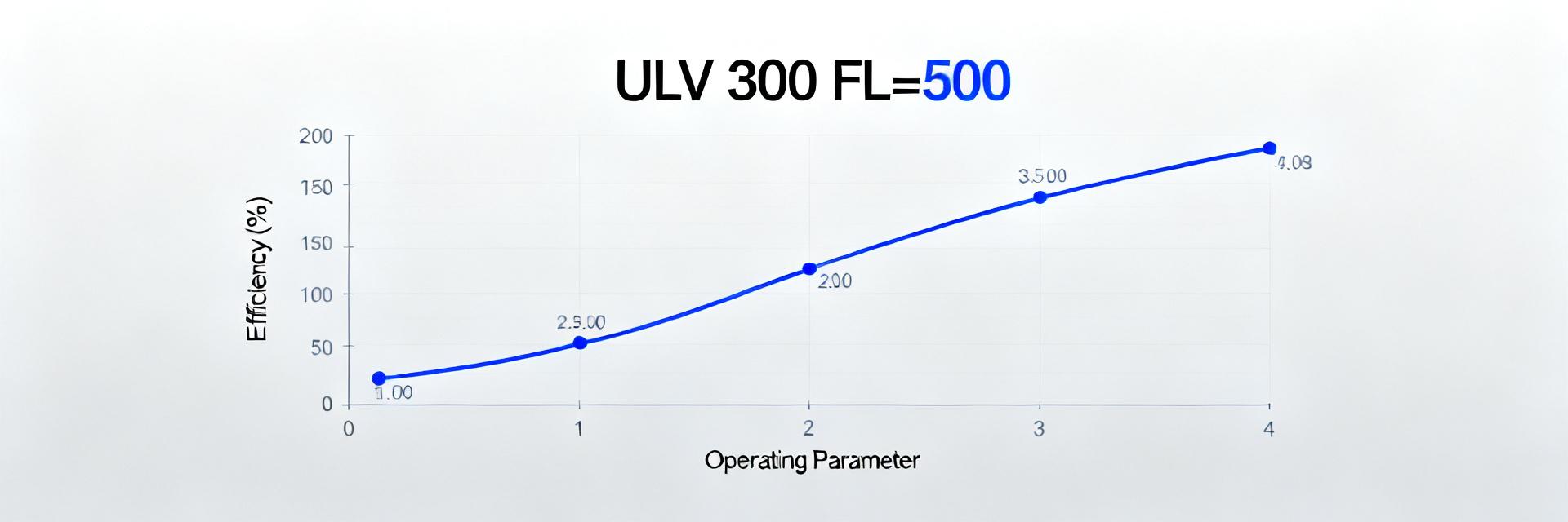
The purpose of this text is to provide a structured, data-driven analysis of the ULH 80 750 J FL=500 resistor's parameters and to highlight which metrics in the datasheet are critical for design. The first section decodes the part numbering and basic electrical characteristics; followed by an analysis of thermal and mounting constraints, and recommendations for measurement and verification.
This material is based on typical datasheet sections and proven engineering methodologies: rated power, resistance, tolerances, TCR, derating curves, and quality control techniques. Practical examples and a checklist will assist in rapid decision-making during component selection and testing.
1 — Overview and Part Number Decoding
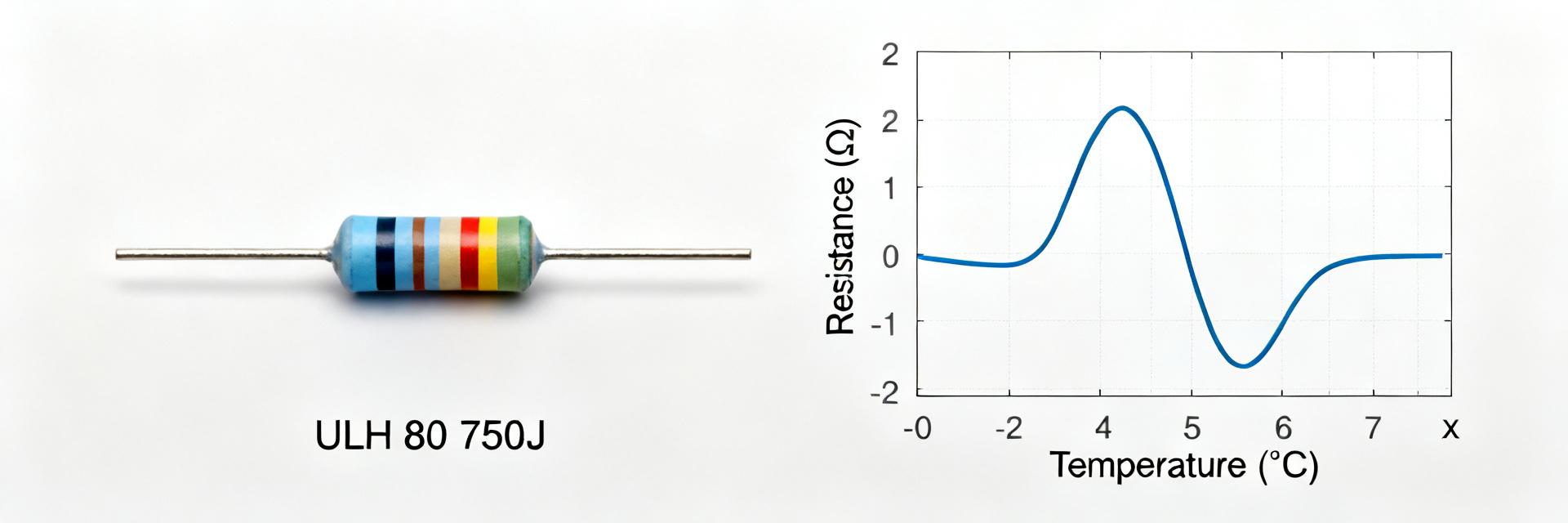
Key point: The part number "ULH 80 750 J FL=500" encodes a set of parameters critical for resistor selection in a circuit. Proof: The marking typically contains the rated power (80 W), nominal resistance (750 Ω), alphabetical tolerance class (J = ±5%), and the FL=500 code, which indicates a functional or mounting characteristic. Explanation: When reading a datasheet, the first step is to identify these four values—Pnom, Rnom, tolerance, and special codes—as they determine the thermal load capacity and project compatibility.
Key point: The practical significance of the FL=500 code lies not just in identification, but in indicating a functional or form-factor feature. Proof: FL codes in this component family often correspond to specific mounting shapes or protective coatings. Explanation: It is critical for the design engineer to cross-reference the FL code in the datasheet with the board's height, mounting, and cooling access requirements; otherwise, the operating temperature and derating calculations will be incorrect.
1.1 — Meaning of the ULH 80 750 J FL=500 Marking
Key point: The key elements of the marking are Pnom, Rnom, tolerance, and the FL code. Proof: Pnom = 80 W indicates high power capability for a specific package form factor; Rnom = 750 Ω defines the electrical resistance; J = ±5% sets the accuracy requirements; and FL=500 indicates a special construction. Explanation: This data primarily impacts the calculation of dissipated power and the choice of mounting configuration.
1.2 — Key Electrical and Mechanical Parameters
Key point: In a datasheet, it is critical to verify the correlation between: nominal value, tolerance, Pnom, TCR, and mounting requirements. Proof: Thermal cycling stability and allowable power dissipation depend on the TCR and enclosure design. Explanation: Even with correct R and P, mismatching the TCR or mounting tolerance can lead to resistance drift and degraded reliability.
| Parameter | Specification | Conditions / Comments |
|---|---|---|
| Rated Power (Pnom) | 80 W | At case temperature not exceeding 25°C |
| Nominal Resistance (Rnom) | 750 Ohm | Base value for the electrical circuit |
| Resistance Tolerance | ±5% (Class J) | Allowable tolerance upon delivery |
| Mounting Modification (FL) | FL=500 | Flexible leads with a length of 500 mm (Flexible Leads) |
2 — Detailed Datasheet Analysis: Electrical Characteristics
Key point: The primary verification of a datasheet begins with confirming the static characteristics: Rnom, tolerance, Pnom, and maximum operating temperature. Proof: A rated power of 80 W sets the upper bound for thermal design; the formula P = I²·R helps estimate current limits. Explanation: Accurate calculation requires accounting for the J = ±5% tolerance and potential measurement variances arising from different methods in the datasheet.
Key point: It is critical to calculate the maximum allowable current and correlate it with the tolerance. Proof: Knowing Rnom and the allowable power yields Imax = sqrt(Pnom/Rnom); this must factor in the tolerance and allowable drift. Explanation: This approach provides a practical value for laboratory verification and defining safety limits in circuits.
2.1 — Rated Power, Resistance, and Tolerances
Key point: Verify that the rated power matches the actual power dissipated under the operating current. Proof: Pnom specifies the value under defined mounting and ambient temperature conditions in the datasheet. Explanation: As the ambient temperature rises, the actual allowable power dissipation drops according to the derating curve; hence, calculations must account for Ta and the actual case/heatsink conditions.
2.2 — Thermal Characteristics and Temperature Limits
Key point: TCR, Tmax, and the derating curve define the resistor's operating regime. Proof: Datasheets typically contain a curve plotting power reduction against rising Ta, and specify Tmax and the operating case temperature. Explanation: For a reliable design, derating must be applied: at elevated Ta, the allowable power drops, which must be factored into the thermal management and mounting calculations.
3 — Tolerances, Reliability, and Test Methodologies
Key point: Testing methodologies in the datasheet describe how nominal stability and thermal endurance are verified. Proof: The characteristics section specifies cycling tests, resistance change after thermal shock, moisture resistance, and mechanical tests. Explanation: Selecting a resistor for critical circuits requires verifying test results and comparing them with actual operating conditions.
Key point: Acceptance criteria after testing determine suitability for application. Proof: Datasheets outline the allowable limits of R change after testing (e.g., ΔR ≤ 0.5% for the series within the test sample). Explanation: This provides laboratory criteria for quality control and helps avoid components prone to high drift.
3.1 — Tolerance Control: Practical Procedures and Measurements
Key point: The standard control algorithm includes verifying R, Pnom, and derating. Proof: Measurements are taken at nominal temperature and after warm-up, then compared against datasheet values. Explanation: A structured sequence of verifications reveals discrepancies and helps determine if screening or additional sampling is necessary.
3.2 — Reliability Testing: Thermal Cycling and Long-Term Operation
Key point: Long-term testing demonstrates stability under real-world thermal cycling. Proof: The datasheet specifies temperatures and cycle counts to evaluate mechanical and electrical drift. Explanation: For high-stress applications, it is recommended to rely on these test results and account for the calculated drift during design.
4 — Typical Application Circuits and Practical Examples
Key point: A resistor with ULH 80 750 J FL=500 specifications is used in dividers, loads, and power matching systems. Proof: High Pnom and tolerance stability make it ideal for shunts and heavy-duty loads. Explanation: When used in dividers, it is critical to ensure proper thermal dissipation and power distribution among elements.
Key point: Mounting and fixing methods directly impact actual power dissipation. Proof: Diagrams illustrate the use of heatsinks, air gaps, and thermal compounds. Explanation: Proper thermal design keeps the operating case temperature within the limits specified in the datasheet, preventing premature failure.
4.1 — Circuit Integration Examples Accounting for Power Dissipation
Key point: The designer must calculate power distribution and provide a derating margin. Proof: Current and dissipated power calculations use P = I²·R and factor in TCR. Explanation: This allows for an early assessment of the need for a heatsink or parallel resistor configurations.
4.2 — Mounting, Fixing, and Heatsink Requirements
Key point: The mounting type and thermal interface directly impact the case temperature. Proof: Datasheets describe permitted mounting conditions and recommended thermal interface materials. Explanation: Employing recommended materials and mounting practices reduces thermal resistance and extends component life.
5 — Selection, Procurement, and Operational Recommendation Checklist
Key point: A datasheet checklist is valuable for quickly verifying that a component meets requirements. Proof: It includes checking R and tolerances, Pnom and the derating curve, TCR, mechanical dimensions, and test conditions. Explanation: Such standardized verification accelerates batch acceptance decisions and reduces the risk of using unsuitable parts.
Key point: When preparing a production test plan, sampling and temperature testing should be incorporated. Proof: The plan typically includes testing 1/3 to 2/3 of the batch, with resampling if deviations are found. Explanation: This balances testing costs with confidence in the quality of the delivered batch.
Conclusion
- Understanding the ULH 80 750 J FL=500 marking is the first step: nominal value, tolerance, Pnom, and the FL code define the primary design constraints.
- In datasheet analysis, the derating curve and TCR are critical—they determine the operating thermal margin and allowable current.
- An engineering checklist accelerates selection: verify R, tolerance, Pnom, derating, and mechanical requirements before acceptance.
- Mounting and thermal management directly affect the actual power dissipation and service life of the resistor.
Frequently Asked Questions
How to verify that the ULH 80 750 J FL=500 conforms to the parameters in the datasheet?
Verification includes measuring the resistance at the nominal temperature, running it at the specified power while monitoring ΔR, comparing it against the J-tolerance class, and evaluating the derating curve under real Ta. It is critical to record the measurement conditions so that the results are comparable to the datasheet values.
Is a heatsink required when operating at 80 W?
Often yes: even if Pnom = 80 W, the actual power dissipation depends on the mounting method and Ta. A reliable calculation requires using the derating curve from the datasheet and evaluating the case-to-ambient thermal resistance. At high Ta, a heatsink or an improved thermal interface material is highly recommended.
What key metrics should be checked in the datasheet before batch acceptance?
The minimum set includes: Rnom and tolerance, Pnom and derating, TCR, mechanical dimensions, and the results of thermal cycling and humidity testing. These metrics provide the technical justification for batch acceptance and further testing.
What does the FL=500 parameter mean in the resistor marking?
The FL=500 parameter in the marking specifies the lead configuration, typically denoting a flexible, heat-resistant lead (Flexible Leads) length of 500 mm. This must be taken into account when evaluating inductive coupling and spatial routing within the enclosure.