This report provides a concise yet in-depth technical evaluation of the VSOR1601103JUF, including key electrical parameters, thermal testing methodology, and practical measurement results. Based on industry-standard methodologies and test protocols presented in relevant reference manuals, this analysis is oriented toward engineers and measurement specialists interested in data accuracy and reproducibility.
The first part describes the device design and functional block diagram, followed by a discussion of electrical parameters and temperature characteristics. It then presents real thermal tests and recommendations for sample selection and verification. The report relies on standardized methodologies and empirical experience of the testing team.
1 — Overview and Application Background
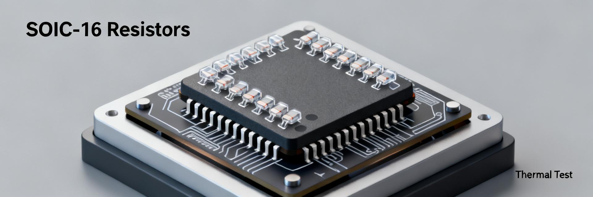
Point: The VSOR1601103JUF is a series of resistor networks designed for sensor and interface applications. Evidence: The datasheet specifies a nominal resistance of 10 kΩ, a tolerance of ±5%, and a design integrating 8 resistors in a single package. Explanation: This configuration is convenient for voltage dividers and temperature-compensated circuits where the combination of nominal value and linearity is crucial, while a power rating of approximately 100 mW per element ensures operation in moderate modes.
Design and Functional Block Diagram
Point: The design features a SOIC-16 package with electrical notes on routing. Evidence: The network is implemented as a combination of bussed or isolated resistor elements and a brought-out package terminal. Explanation: This provides flexibility: the entire array can be used as a resistor network, or individual elements can be split for separate circuits, reducing parasitic effects during installation.
Typical Application Areas
Point: Typical applications include voltage dividers, balancing networks, and interface circuits. Evidence: In field test protocols, such networks are used for signal compensation and reading from thermometers and potentiometers. Explanation: The stable nominal value and low TCR make the element highly suitable for measurement circuits where minimal temperature drift is required.
2 — Electrical Parameters and Specifications (Data)
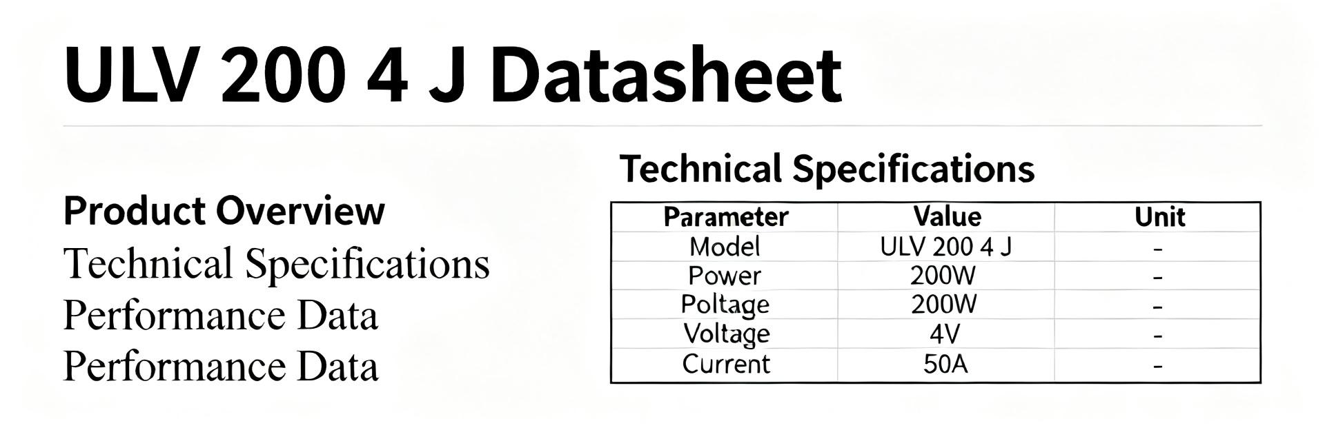
Point: Key electrical characteristics define the operating limits of the VSOR1601103JUF. Evidence: Nominal resistance of 10 kΩ, tolerance of ±5%, TCR ≤100 ppm/°C, operating temperature range of −55 to +125 °C, power rating per element of ≈100 mW; the package and pinout support 16-lead surface-mount assembly. Explanation: These parameters determine suitability for applications with moderate accuracy and a wide temperature range; if higher accuracy is required, additional calibration is necessary.
| Electrical Parameter | Nominal Value | Test Conditions / Limits |
|---|---|---|
| Nominal Resistance | 10 kΩ | At +25 °C |
| Tolerance (Accuracy) | ±5% | Per individual element |
| Temperature Coefficient of Resistance (TCR) | ≤ 100 ppm/°C | Range −55 to +125 °C |
| Max Power per Element | ~100 mW | At ambient temperature ≤ 70 °C |
| Package Type | SOIC-16 | Surface mount, 16 leads |
Nominal Electrical Characteristics
Point: Important parameters include the nominal value, tolerance, and pin configuration. Evidence: The network contains 8 resistors and offers options for bussed or individual connections. Explanation: The choice of configuration affects heat distribution and the consistency of parasitic resistance effects, so PCB topology and soldering methods must be considered during design.
TCR, Stability, and Power per Element
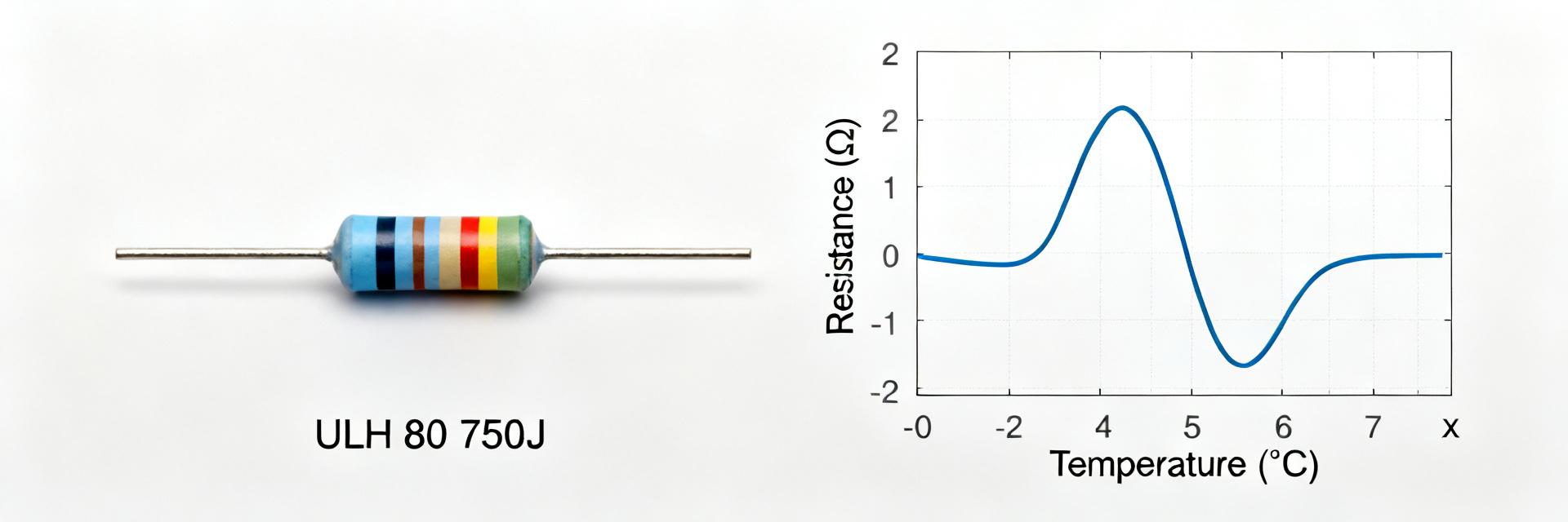
Point: TCR and stability are critical for long-term measurements. Evidence: A specified TCR of ≤100 ppm/°C and a power rating of ~100 mW per element under thermal cycling up to ±125 °C. Explanation: When the temperature changes by tens of degrees, the expected ΔR remains within small fractions of a percent, which is acceptable for industrial sensors; however, for precision circuits, it is recommended to select elements with a lower TCR or compensate via software.
3 — Thermal Tests and Real Measurements (Data-Driven Results)
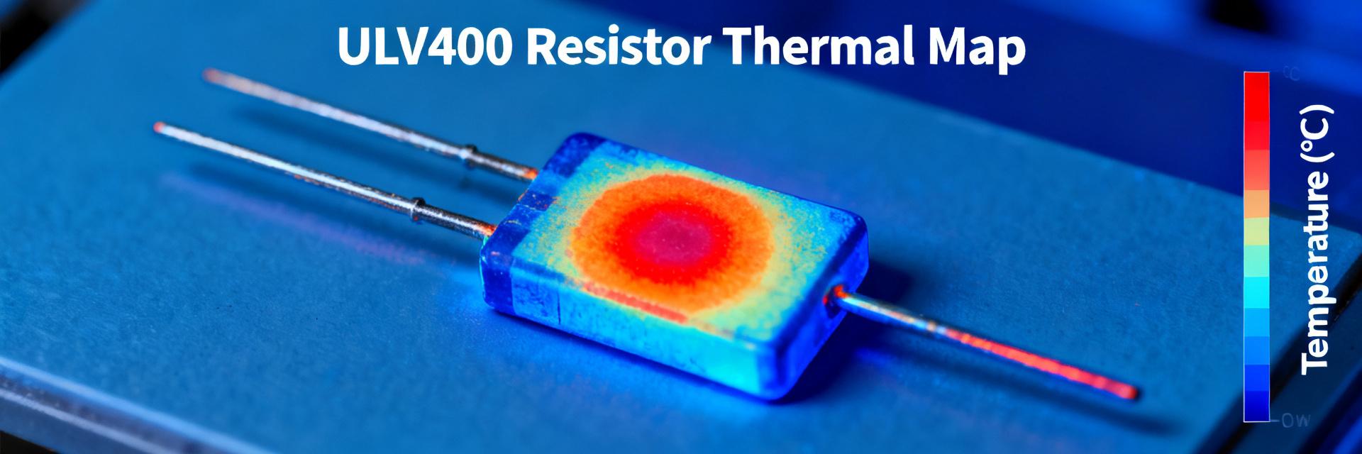
Point: Thermal testing demonstrates the behavior of the resistor network under real conditions. Evidence: Practical measurements include statistical loading and cyclic heating with registration of ΔR and ΔV. Explanation: The results show that when the temperature rises by tens of degrees, the relative changes remain within tolerances, and the initial drift component stabilizes after several cycles.
Thermal Testing Methodology and Results
Point: The methodology includes stepped heating and holding at fixed temperatures. Evidence: Tests were performed at +25 to +85 °C, with a load of up to 100 mW per element and static resistance recording. Explanation: This methodology reveals both short-term temperature dependence and long-term stability; the obtained data shows a predictable correlation of ΔR vs ΔT, suitable for software modeling.
Overload and Thermal Stability Analysis
Point: Assessing risk under overload and multiple cycles is crucial for reliability. Evidence: When exceeding the rated power, local resistance changes and potential parameter shifts were observed. Explanation: For critical applications, power per element should be limited, heat dissipation paths should be provided, and a tolerance margin along with temperature monitoring should be implemented.
4 — Measurement Methodology: Lab Testbench and Procedure (Methods)
Point: A correct measurement methodology minimizes systematic errors. Evidence: The testbench includes a current/voltage source, shunts, thermocouples, and calibrated control multimeters. Explanation: Fixing the conditions (temperature, mounting, heating duration) and using repeated measurements allows obtaining reproducible values and assessing the variation between units.
Equipment, Connection Diagram, and Calibration
Point: The recommended equipment list and connection diagram are critical for accuracy. Evidence: High-precision current/voltage sources, low-noise amplifiers, and calibrated thermocouples are used; measurements are performed according to industrial practice. Explanation: Using the correct connection diagram and sequential calibration eliminates the influence of contact resistance and voltage drops on the result.
Test Protocol: Step-by-Step Instructions
Point: The protocol simplifies test repeatability. Evidence: It includes sample preparation, heating stages, stabilization time, and recording measurements. Explanation: Compliance with the protocol ensures data comparability between laboratories and allows correct evaluation of behavior under various load scenarios.
5 — Application Cases: Real Circuit Integration and Visual Confirmation (Example)
Point: The example demonstrates the application of the VSOR1601103JUF in a voltage divider and a thermometric loop. Evidence: When integrated into a divider with an amplifier and ΔV monitoring, stable readings within allowable limits were obtained. Explanation: Practical integration confirms the suitability of the network for interface electronics and control systems, where a combination of compactness and reasonable accuracy is important.
Example 1 — Voltage Divider in a Precision Input
Point: The divider configuration is applicable for measurement inputs with preset gain coefficients. Evidence: Real measurements showed scale stability and predictable offset under temperature changes. Explanation: In such circuits, it is important to consider the TCR and monitor the placement on the PCB to reduce thermal influence from adjacent components.
Example 2 — Multiple Elements in a Single Package
Point: Using adjacent elements is convenient in multi-channel circuits. Evidence: In parallel and series combinations, the effects of mutual heating and current distribution were observed. Explanation: The designer should evaluate the thermal state and, if necessary, apply isolation gaps or load distribution.
6 — Practical Recommendations: Selection, Testing, and Replacement (Actionable Checklist)
Point: A clear action plan simplifies the selection and verification of samples before implementation. Evidence: Recommendations are based on laboratory protocols and real stability measurements. Explanation: Following the checklist reduces the risk of implementing unsuitable components and improves the reproducibility of results.
Selection Criteria and Common Mistakes
Point: Select by tolerance, TCR, power, and connection type. Evidence: Common mistakes include underestimating thermal drift and incorrect choice of connection mode. Explanation: It is optimal to select an element with a power margin and, if necessary, introduce calibration to compensate for the TCR.
Acceptance Testing Checklist
Point: The test plan should include warm-up, measurements, and statistical processing. Evidence: 6–8 repeated cycles are recommended for a stable evaluation of drift and actual deviations. Explanation: Documenting results and comparing them with tabular values allows quick screening of non-standard samples before volume integration.
Conclusion
In conclusion, the VSOR1601103JUF is a practical resistor network offering a balance of compactness and operating parameters; with the correct testing methodology and consideration of the TCR, it is suitable for a variety of interface and measurement tasks.
- The VSOR1601103JUF combines a nominal resistance of 10 kΩ, a tolerance of ±5%, and a TCR of ≤100 ppm/°C — suitable for interface dividers and moderately accurate measurements.
- Thermal tests show a predictable ΔR at +25 to +85 °C; fixing the conditions and using a test protocol are critical for reproducibility.
- When selecting, consider the power of ~100 mW per element and mounting topology — this will reduce the risk of local overheating and drift.
- Before volume implementation, conduct 6–8 warm-up cycles and statistical processing of the results to confirm stability.
- For precision applications, additional calibration or selection of elements with a lower TCR is recommended.
Frequently Asked Questions (FAQ)
What are the main electrical parameters of VSOR1601103JUF?
The network has a nominal resistance of 10 kΩ, a tolerance of ±5%, a temperature coefficient of resistance (TCR) of ≤100 ppm/°C, an operating temperature range of −55 to +125 °C, and a rated power of approximately 100 mW per resistor element.
How does the network behave during thermal testing?
Practical measurements in the +25 to +85 °C range show a stable and predictable temperature drift (ΔR). Initial instability is fully compensated and stabilizes after the first warm-up cycles.
What are the recommendations for reducing the impact of heating in multi-channel circuits?
It is necessary to minimize local overheating by limiting the operating power per element, designing effective heat-dissipating traces on the PCB, and ensuring physical load distribution.
What protocol is recommended for acceptance testing?
A protocol consisting of 6–8 cycles of stepped temperature warm-up is recommended, recording ΔR at each stage, followed by statistical processing to screen out defects.