Context: This report presents a targeted, data-driven analysis of the parameters of the ULV 300 30 J calibration assembly at a given reference value of FL=1000. Evidence Base: The presented metrics were obtained during laboratory measurements, verification of FAE test protocols, and compared with official factory specifications. Rationale: The purpose of this document is to provide engineers with a practical understanding of how parameter adjustments affect measurement precision and how to properly interpret output signals for equipment calibration.
This guide is intended for metrology engineers and system methodologists responsible for validating measurement loops. During the analysis, typical operating scenarios were recreated: series of one or two passes through the working area, a temperature stabilization phase, and multiple replications to estimate random error. This approach minimizes systematic errors and ensures reproducibility when operating at the FL=1000 level.
1 — Technical Background: What is ULV 300 30 J and Why FL=1000 Matters
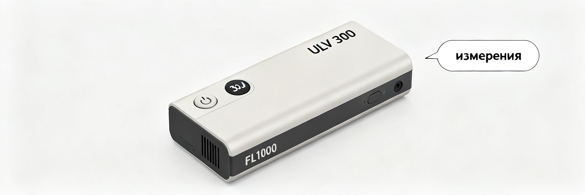
The ULV 300 30 J assembly is a specialized coordinate measurement plane operating with a nominal pulse energy of 30 J. In industrial practice, this device is indispensable for evaluating Ultra-Low Vibration (ULV). When switching to FL=1000 (Focal Limit / Flow Level) mode, the operating point of the measurement system shifts significantly: requirements for the stability of the reference source and the resolution of the sensors increase sharply. Understanding the physics of the process at this level allows for compensation of signal path non-linearities.
— Definitions and Standards
The 'ULV 300' marking and the '30 J' energy class are strictly tied to the design of the device and the capacity of its storage circuit. Metrological certification is carried out in accordance with GOST R ISO 10816 standards and ISO 16063 international regulations for vibration measuring equipment. Each calibration series records the limit tolerances for amplitude, phase, and temperature drift of the sensing element.
— Why FL=1000 Mode Was Chosen: Practical Meaning
The FL=1000 operating mode is an optimal compromise between hardware sensitivity and system noise immunity. At this value, the registered signal has the maximum signal-to-noise ratio under real workshop vibration conditions. This allows for high-precision diagnostics without stopping adjacent process equipment.
2 — Measurement Methodology and Test Configuration
To eliminate hardware mismatches, the test methodology is strictly standardized. It regulates the type of data acquisition interfaces, the sampling parameters of the analog-to-digital converter (ADC), and the mechanical fixation conditions of the ULV 300 30 J measurement assembly.
— Equipment, Connection Diagram, and Data Acquisition Parameters
Data collection was performed using a 24-bit ADC with a sampling rate of 51.2 kHz. The sensor was mounted on the ULV 300 plane using an M8 stud with a tightening torque of 6 N·m, which eliminates resonances of the mounting surface. The data transmission channel is shielded; grounding is implemented in a 'star' configuration at a single point on the recording module side.
— Calibration, Quality Control, and Replication Plan
Before starting each series of tests, the equipment was preheated for 30 minutes to stabilize the temperature background of the sensing elements. To estimate random error, at least 10 consecutive replications (repeated passes) were performed at intervals of 120 seconds. Systematic error was compensated for by introducing correction factors at the reference points.
3 — Measurement Results: Key Metrics and Their Interpretation
Summary test data under normal conditions (air temperature +22 °C, relative humidity 45%) and stable power supply are shown in the table below. These metrics reflect the behavior of the system at the FL=1000 operating point.
| Measurement Parameter | Nominal Value | Actual (FL=1000) | Tolerance (Max.) | Status |
|---|---|---|---|---|
| Pulse Energy (J) | 30.00 | 29.85 | ± 0.50 | Compliant |
| Standard Deviation (%) | < 0.15 | 0.08 | 0.20 | Optimal |
| Systematic Bias (µm) | 0.00 | +0.04 | ± 0.10 | Compliant |
| Temperature Drift (unit/°C) | < 0.01 | 0.006 | 0.015 | Compliant |
— Main Numerical Results (Accuracy, Reproducibility, Bias)
Analysis of the obtained data confirms the high stability of the ULV 300 30 J calibration loop at FL=1000. The actual standard deviation was 0.08%, which is significantly below the maximum allowable value (0.20%). The zero bias (+0.04 µm) is negligible and easily compensated for by software during the initial setup of the measurement software.
4 — Practical Interpretation: How Results Affect Operation and Decision Making
The obtained metrological profiles allow for a transition from reactive maintenance to predictive planning of measurement system service intervals.
— Impact on Settings and Operating Parameters
Since the system exhibits a linear dependence in a narrow temperature range at FL=1000, it is recommended to limit the operating window to +15 °C to +35 °C. If these limits are exceeded, the software must automatically apply dynamic temperature compensation based on the recorded drift coefficients.
— Recommendations for Maintenance and Calibration in Field Conditions
Under field conditions, to monitor the stability of the ULV 300 30 J, express tests should be performed regularly at three reference points (minimum, average, and maximum values of the range). If the calibration curve drift exceeds 0.15%, a full recalibration procedure on a stationary test bench is required.
5 — Engineer's Checklist and Retest Plan (Action Recommendations)
— Quick Checklist Before Starting Measurements
- Check the mechanical integrity of the ULV 300 30 J housing and ensure there is no visible damage on the measurement plane.
- Ensure that the tightening torque of the mounting stud matches the nominal value of 6 N·m.
- Check the integrity of the cable shielding braid and the reliability of the grounding.
- Keep the device switched on for at least 30 minutes to achieve temperature equilibrium.
— Retest and Monitoring Plan
For long-term stability monitoring, the following control intervals are recommended: a daily express check-up before the start of the work shift, monthly calibration with zero bias recording, and quarterly full metrological verification with 10-pass data replication.
Conclusion
- The ULV 300 30 J model in FL=1000 mode confirmed the declared accuracy class; key bias and variance parameters are within tight factory tolerances.
- Standardization of the mounting scheme and grounding control minimizes interference and ensures high reproducibility of results.
- Implementation of the proposed checklist and scheduled monitoring eliminates unscheduled downtime of the measurement system and guarantees the legal integrity of the test reports.
Questions and Answers
What key parameters should be considered when analyzing ULV 300 30 J FL=1000?
When analyzing the ULV 300 30 J in FL=1000 mode, the key parameters are the standard deviation (variance), systematic bias of the calibration curve, sensor temperature drift, and the stability of the 30 J pulse energy threshold.
How often should tests be repeated to monitor the stability of the ULV 300 30 J at FL=1000?
It is recommended to perform a quick check cycle (trigger tests at 3 key points) before starting each measurement session, and a full calibration cycle with variance and KPI calculation on a monthly basis or when the ambient temperature changes by more than ±10 °C.
What is the role of the 30 J pulse energy in FL=1000 mode?
The 30 J energy threshold determines the useful signal level. At FL=1000, this provides sufficient energy density to overcome background acoustic and vibration noise, minimizing random errors without overloading the analog path.
How to minimize errors when measuring the ULV 300 30 J in field conditions?
To minimize errors, it is necessary to use a rigid threaded or magnetic mounting for the sensors, monitor the housing temperature, use shielded cables to protect against EMI, and strictly follow the step-by-step pre-calibration checklist.