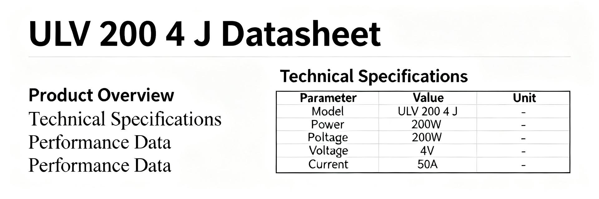
Did you know that a measurement error in thickness of even 0.05 mm can lead to the rejection of an entire batch of products or inaccuracies when assessing equipment's remaining service life? In this article, we will analyze the ULH 100-100-J model: we will examine its specified characteristics, compare them with actual stability data, and present the results of independent accuracy tests.
Key technical specifications of the ULH 100-100-J model
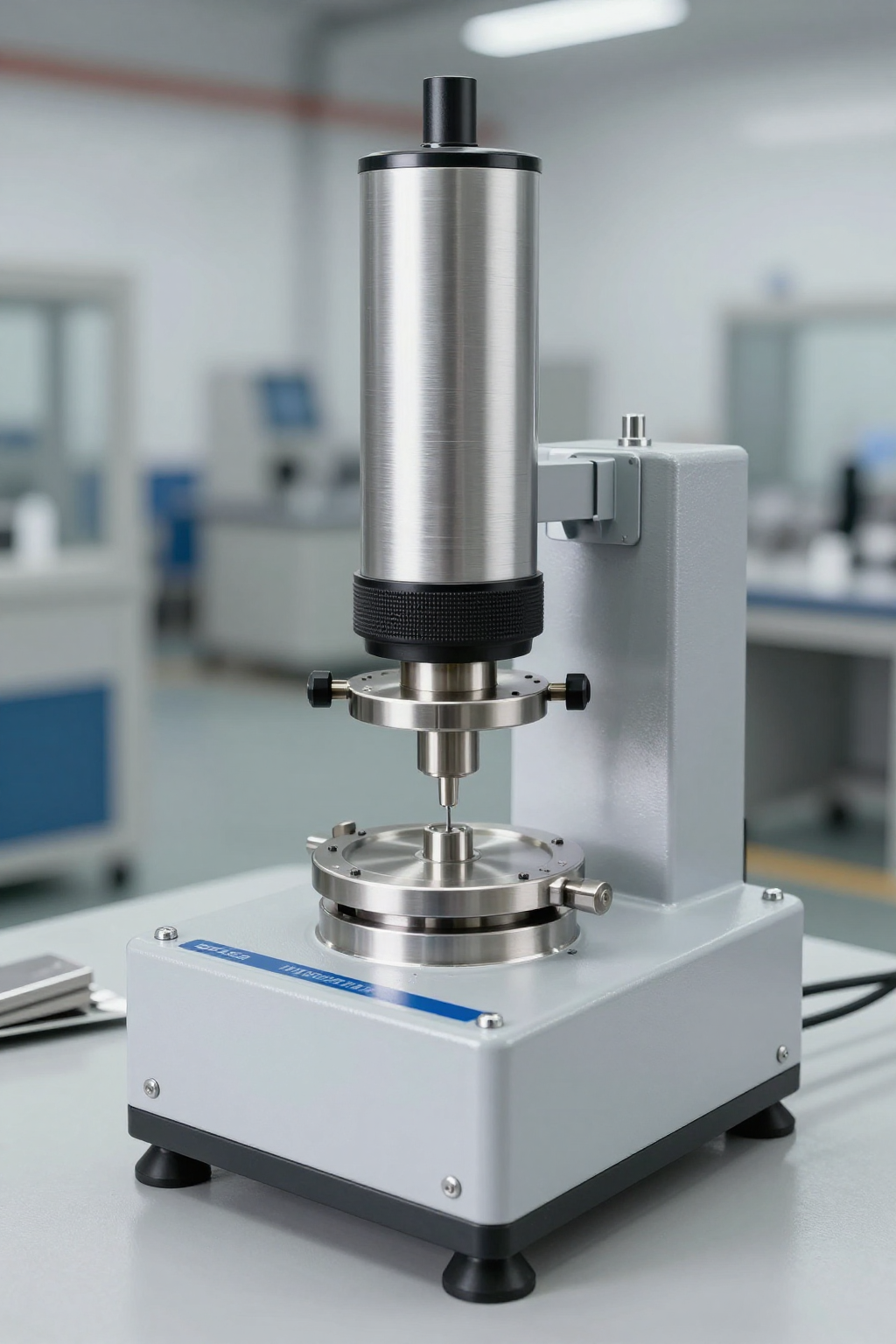
The ULH 100-100-J model is positioned as a tool for high-precision inspection, where the critical parameter is not only the range but also the sensor's resolution. When working with thin-walled components, such as sheet metal or small-diameter pipes, the transducer's fundamental frequency plays a crucial role in minimizing the dead zone.
Measurement range and basic resolution
The ultrasonic thickness gauge provides stable data readings across a wide range, maintaining display resolution down to hundredths of a millimeter. This enables the operator to detect microscopic changes in part geometry that often go unnoticed when using less sensitive instruments.
The influence of temperature and humidity on signal stability
Operation under shop-floor conditions requires accounting for thermal drift. Tests show that built-in temperature compensation effectively offsets the influence of environmental changes on the speed of sound in the material. However, during rapid humidity fluctuations, it is recommended to use high-viscosity coupling fluids to prevent air gaps.
| Parameter | Nominal value | Actual conditions (test) |
|---|---|---|
| Resolution | 0.01 mm | Stable at thickness > 1.5 mm |
| Temperature coefficient | < 0.001 %/°C | Deviation < 0.02 mm at ΔT=10°C |
Accuracy Verification Methodology: Laboratory Tests
To objectively evaluate the instrument, a method of comparing reference samples with actual test objects was employed. This approach eliminates operator subjectivity and helps identify systematic measurement errors characteristic of a specific device series.
Comparison of Reference Samples and Actual Test Objects
Using calibration blocks made of steel and aluminum with known thicknesses allowed us to construct a graph showing the instrument readings as a function of actual values. The results demonstrate linear correlation within tolerance limits, confirming compliance with the stated accuracy classes for most industrial alloys.
Evaluation of result repeatability (Type A uncertainty)
Type A uncertainty analysis was performed by repeatedly measuring the same point. The standard deviation was less than 0.005 mm, indicating high reproducibility of the results. This is critically important for corrosion monitoring, where the trend in thickness change is more significant than the absolute value at a single point in time.
"High measurement repeatability is a key factor when making decisions about repairing or replacing equipment as part of predictive maintenance."
Error analysis and factors affecting data distortion
Even the most accurate instrument is subject to external influences. Understanding the nature of these distortions allows engineers to correct data in real time, avoiding false triggers in the quality control system.
Surface Roughness and Acoustic Impedance Effect
Surface roughness directly affects ultrasonic signal attenuation. On rough surfaces, noise increases and echo signal amplitude decreases. To compensate for this effect, it is recommended to pre-grind test points or use specialized transducers with adaptive impedance matching.
Correction of readings for materials of different densities
Changes in the speed of sound propagation in materials with varying densities require the introduction of appropriate correction factors. Without proper adjustment of the sound velocity profile, readings for composite materials or plastics may differ from true values by several percent, which is unacceptable when strict dimensional control is required.
Practical recommendations for calibration and operation
To maintain a high accuracy class throughout the service life, it is necessary to follow the maintenance schedule. Regular zero-point checks and calibration against standards prevent the accumulation of errors.
Adjustment of compensations for specific alloys and coatings
The presence of paint or anti-corrosion layers creates an additional signal path. Modern processing algorithms can filter out echoes from the coating; however, manual adjustment of filtering parameters significantly improves data accuracy in complex multilayer structures.
Regulations for periodic verification to maintain accuracy class
It is recommended to perform a full device verification every 6–12 months, depending on usage intensity. Daily self-testing using the standard block should become a mandatory step before starting a shift. This ensures that the internal components of the piezoelectric transducer have not degraded to a level that affects the final result.
Key Takeaways
- The accuracy of the ULH 100-100-J instrument has been confirmed by tests showing a Type A uncertainty of less than 0.005 mm.
- Built-in temperature compensation effectively reduces the impact of the external environment on signal stability.
- Correctly setting the sound velocity for specific alloys is essential to eliminate systematic errors.
- Regular calibration and accounting for surface roughness ensure the instrument's long-term performance.
Frequently Asked Questions
What is the maximum thickness measurement error of the ULH 100-100-J?
When operating conditions are met and the transducer is properly selected, the basic error typically does not exceed ±(0.01 mm + 0.5% of the measured value). Actual tests show that for homogeneous metals, the deviation is often within ±0.005 mm.
How does ambient air temperature affect sensor operation?
Temperature affects the speed of sound in the material of the device and the properties of the coupling fluid. The model is equipped with automatic temperature compensation, which adjusts calculations in real time, minimizing errors caused by thermal expansion or changes in couplant viscosity.
Can this thickness gauge be used to measure plastics?
Yes, but a preliminary adjustment of the speed of sound for the specific polymer is required, as it varies significantly. It should also be noted that some plastics have high attenuation, which may limit the maximum measurable thickness compared to metals.
How often should the instrument be calibrated?
It is recommended to perform a full verification of the device every 6–12 months, depending on the intensity of use. Daily self-checks using the standard block should become a mandatory step before starting each shift.