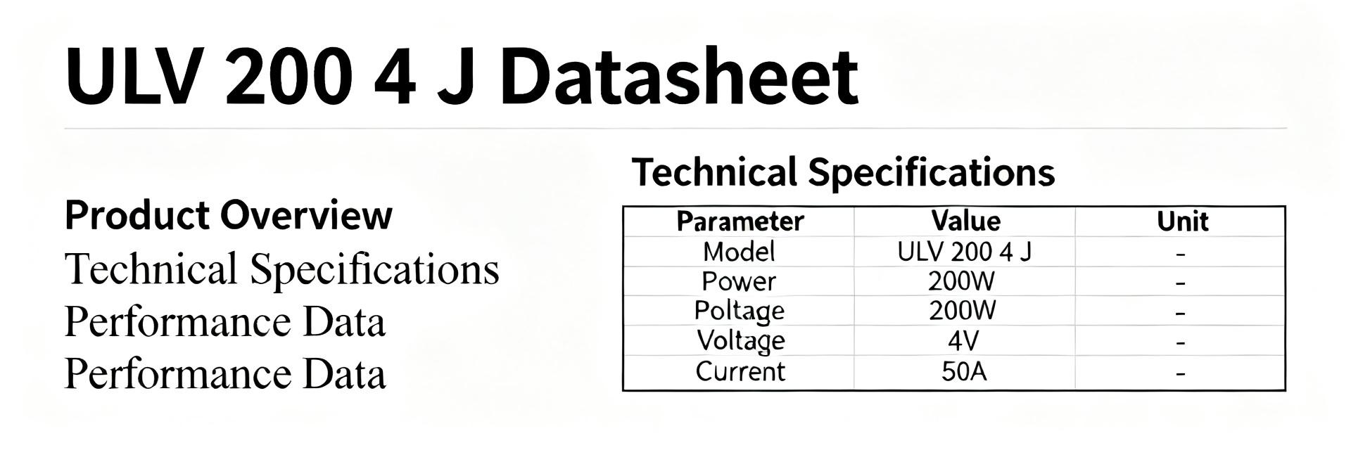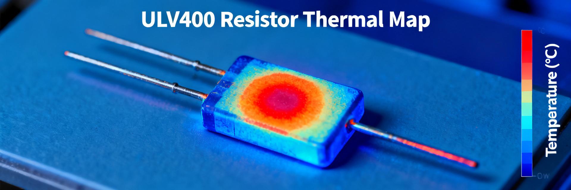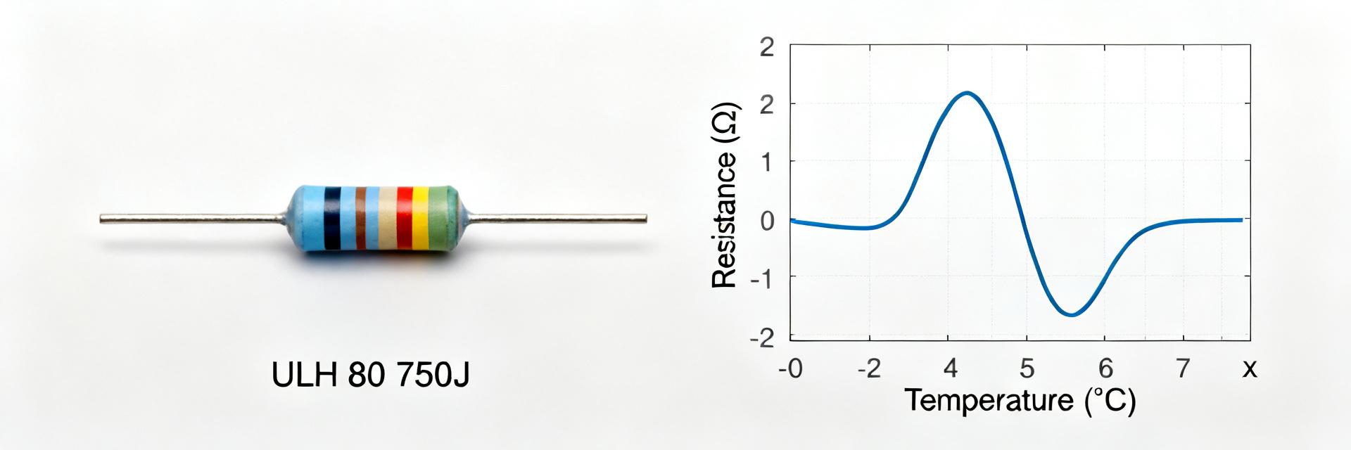
The ORNTA1001ZUF precision resistor network is a high-tech component with strictly defined electrical characteristics. A critical engineering task during its integration is to correctly analyze and interpret the original datasheet to ensure accurate selection of companion components. At the initial design stage, it is crucial to establish nominal values, tolerance types, and mounting requirements based on the manufacturer's official specifications.
Analysis of engineering practice shows that a systematic approach—from verifying basic parameters to detailed tolerance budget calculation—minimizes the risk of design errors. Sequential verification of parameters before launching PCB production significantly reduces defect rates and eliminates the need for costly redesigns.
1 — Purpose and Applications of the Precision Network
Brief Purpose and Typical Application Areas
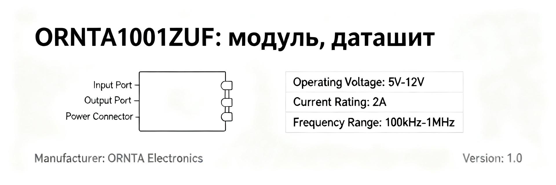
Concept: The ORNTA1001ZUF module is positioned as a highly stable element for analog interface and measurement circuits. Justification: Technical catalogs from Vishay Thin Film indicate the widespread use of this network in precision voltage dividers, measurement bridges, telemetry, and industrial sensor nodes. Explanation: Due to its high temperature stability and resistor matching, this component is indispensable for signal filtering and conditioning in compact measuring instruments.
Key Operating Limits
Concept: The network has strict environmental and physical limits that must be observed to maintain accuracy. Justification: Limits on maximum junction temperature, ambient humidity, and mechanical deformation are regulated by quality standards. Explanation: Violation of the thermal regime leads to irreversible drift of nominal values. Knowing these limits allows the engineer to correctly choose PCB geometry and protective coating class.
2 — Overview of Key Parameters in the ORNTA1001ZUF Datasheet
Electrical and Functional Parameters
Concept: The network specification defines precise resistor values, matching parameters, and limit electrical conditions. Justification: According to the documentation, the base resistance of each leg is 1000 ohms (1 kΩ), and mutual resistor mismatch is minimized due to the single silicon die. Explanation: Ideal matching (Ratio Tracking) ensures that when external conditions change, the divider legs change synchronously, keeping the division ratio constant.
| Parameter | Nominal Value | Absolute Tolerance | Ratio Tolerance |
|---|---|---|---|
| Resistance R1, R2 | 1000 Ohm (1 kΩ) | ± 0.1% | ± 0.05% |
| Temp. Coefficient (TCR) | ± 25 ppm/°C | - | ± 5 ppm/°C (TCR Tracking) |
| Power Dissipation | 100 mW per resistor | - | - |
| Operating Temperature Range | -55°C ... +125°C | - | Ratio Stability < 0.02% |
Mechanical and Environmental Parameters
Concept: SOIC-8 package dimensions and footprint determine the structural reliability of the assembly. Justification: Datasheet drawings regulate the physical dimensions of the leads and coplanarity tolerances. Explanation: Exact adherence to recommended land pattern sizes ensures high-quality solder reflow and eliminates parasitic mechanical stress on the die.
3 — How to Read and Interpret Tolerances and Errors
Tolerance Types in the Datasheet and Their Designations
Concept: The designer must clearly distinguish between the absolute tolerance of an individual resistor and the ratio tolerance of a divider pair. Justification: The Vishay datasheet provides two different values: absolute tolerance (e.g., ±0.1%) and ratio tolerance (up to ±0.05%). Explanation: When designing a precision amplifier, the ratio tolerance is critical because it determines the accuracy of the overall circuit gain.
Translating Tolerances into Design Requirements (Tolerance Budget)
Concept: The 'Tolerance Budget' method allows mathematical summation of all possible sources of circuit instability. Justification: Systematic calculation includes initial tolerance, temperature coefficient (TCR), load life drift, and humidity effects. Explanation: Summing the worst-case errors using the RSS (Root-Sum-Square) method provides an objective assessment of device accuracy throughout its lifecycle.
4 — Parameter Verification Methods and Tolerance Checking
Measurement Protocol: Steps and Equipment
Concept: Verification of precision components requires specialized metrological equipment. Justification: Conventional multimeters cannot be used to detect deviations of around ±0.05%; precision 6.5- or 7.5-digit voltmeters with a four-wire Kelvin connection are required. Explanation: Measurements are conducted in a temperature-controlled chamber to eliminate the influence of laboratory ambient temperature fluctuations.
Common Measurement Errors and How to Eliminate Them
Concept: Ignoring lead parasitic resistance and thermoelectric EMF (thermal EMF) distorts test results. Justification: Contact junctions of dissimilar metals in the presence of a temperature gradient act as thermocouples, adding microvolt noise. Explanation: Using high-quality copper test clips and offset compensation completely neutralizes these errors.
5 — Practical Selection and Calculation Example with ORNTA1001ZUF
Quick Case Study: Component Selection for a Specific Task
Concept: Consider designing a differential amplifier input stage with a Common-Mode Rejection Ratio (CMRR) greater than 80 dB. Justification: Standard discrete resistors with 0.1% tolerance cannot provide a CMRR higher than 60 dB due to random value distribution. Explanation: Integrating the ORNTA1001ZUF network with a matched ratio solves this problem without manual circuit trimming on the production line.
Verification of Tolerance Chain: An Example
Concept: Let's calculate the division ratio error over a temperature change of 50°C. Justification: Thanks to the TCR Tracking parameter of ±5 ppm/°C, the maximum temperature drift of the ratio is only 0.025%. Explanation: Using discrete precision resistors with individual drifts of ±25 ppm/°C would result in a worst-case drift of up to 0.25%, which is 10 times worse than the ORNTA1001ZUF-based solution.
6 — Practical Checklist: Pre-production and Operation
Pre-production Control
Concept: Before PCB assembly begins, Gerber files and the assembly process card must be verified. Justification: Errors in thermal relief pad design can cause uneven heating of the resistors inside the package. Explanation: Symmetrical connection of traces to the network leads minimizes thermal gradients and preserves the precision properties of the die.
Operating Recommendations and Monitoring
Concept: During device operation, periodic monitoring of key reference voltages is recommended. Justification: Monitoring parameter drift allows timely detection of solder joint or PCB degradation under vibration. Explanation: Preventive analysis of telemetry data prevents sudden failure of the measurement system.
Conclusion
- Brief Summary: In-depth study of the ORNTA1001ZUF datasheet, accounting for ratio tolerance, and calculating the total tolerance budget guarantees high accuracy of the designed measurement circuits.
- Practical Value: A standardized incoming inspection procedure and network parameter verification protect the project from hidden defects during mass production.
- Key Recommendation: Always include a safety margin in calculations and prioritize the TCR Tracking parameter when operating over a wide temperature range.
Frequently Asked Questions (FAQ)
How to verify ORNTA1001ZUF compliance with declared parameters?
Verification starts by comparing nominal values and ranges, followed by a series of measurements under controlled conditions, and calculating the total tolerance budget. The results are recorded in a report, based on which system calibration is performed.
Which datasheet parameters are primary when selecting components?
When selecting, voltage and current levels, temperature limits (TCR Tracking), input/output types, and physical package dimensions are critical. The specific priority is determined by project requirements.
How to minimize the risk of non-compliance in mass production?
To minimize defects, it is necessary to implement pre-production control, use standardized test procedures, calculate the cumulative error, and allocate a safety margin for companion components.
What are the key features of the precision tolerances of the ORNTA1001ZUF network?
The main feature is the tight ratio tolerance (Ratio Tolerance up to ±0.05%) and minimal mutual resistance drift (TCR Tracking ±5 ppm/°C), which guarantees high stability of the division ratio.